
Page 14 - A Primer of Oilwell Drilling, 7th Edition
P. 14
ormal drilling operations include drilling the hole and adding a
Nnew joint of pipe as the hole deepens. it also involves tripping 10
Petroleum Extension-The University of Texas at Austin
the drill string out the hole to put on a new bit and then running it
back to the bottom (making a round trip). Other key steps include
running and cementing the large-diameter steel casing used to seal
selected intervals of the hole.
Normal
dRILLINg THE SURfaCE HOLE
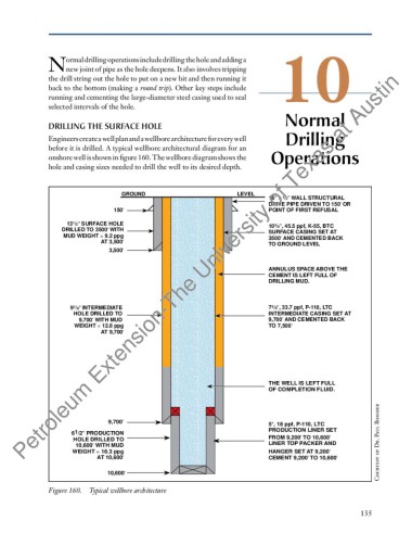
Engineers create a well plan and a wellbore architecture for every well drilling
before it is drilled. A typical wellbore architectural diagram for an
onshore well is shown in figure 160. The wellbore diagram shows the Operations
hole and casing sizes needed to drill the well to its desired depth.
GROUND LEVEL
1
16'' x /2'' WALL STRUCTURAL
DRIVE PIPE DRIVEN TO 150' OR
150' POINT OF FIRST REFUSAL
1
13 /2'' SURFACE HOLE 10 3 /4'', 45.5 ppf, K-55, BTC
DRILLED TO 3500' WITH SURFACE CASING SET AT
MUD WEIGHT = 9.2 ppg 3500' AND CEMENTED BACK
AT 3,500' TO GROUND LEVEL
3,500'
ANNULUS SPACE ABOVE THE
CEMENT IS LEFT FULL OF
DRILLING MUD.
9 7 /8'' INTERMEDIATE 7 5 /8'', 33.7 ppf, P-110, LTC
HOLE DRILLED TO INTERMEDIATE CASING SET AT
9,700' WITH MUD 9,700' AND CEMENTED BACK
WEIGHT = 12.8 ppg TO 7,500'
AT 9,700'
THE WELL IS LEFT FULL
OF COMPLETION FLUID.
aul Bommer
9,700' 5'', 18 ppf, P-110, LTC
PRODUCTION LINER SET
6 1 /2'' PRODUCTION
HOLE DRILLED TO FROM 9,200' TO 10,600' P
10,600' WITH MUD LINER TOP PACKER AND
WEIGHT = 16.3 ppg HANGER SET AT 9,200' tesy of Dr.
AT 10,600' CEMENT 9,200' TO 10,600'
Cour
10,600'
Figure 160. Typical wellbore architecture
135